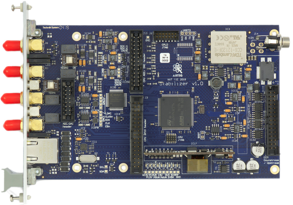
2.8 KiB
2.8 KiB
Stabilizer Firmware
Features
- dual channel
- SPI ADC
- SPI DAC
- 500 kHz rate, timed sampling
- 2 µs latency, unmatched between channels
- f32 IIR math
- generic biquad (second order) IIR filter
- anti-windup
- derivative kick avoidance
Limitations/TODOs
- Fixed AFE gains
- The IP and MAC address are hardcoded
- Expose configurable limits
- 100Base-T only
- Digital IO, GPIO header, AFE header, EEM header are not handled
Hardware
See https://github.com/sinara-hw/Stabilizer
Minimal bootstrapping documentation
- Clone or download this
- Get rustup
- Get cargo-binutils
rustup target add thumbv7em-none-eabihfcargo build --release- Do not try the debug (default) mode. It is guaranteed to panic.
Using GDB/OpenOCD
- Get a recent openocd, a JTAG adapter ("st-link" or some clone) and everything connected and permissions setup. Most Nucleo boards have a detachable ST-Link v2 and are cheap.1
- Get a multiarch
gdb(or a cross arm gdb and edit.cargo/configaccordingly) openocd -f stabilizer.cfgand leave it runningcargo run --release
Using USB-DFU
- Install the DFU USB tool (
dfu-util) - Connect to the Micro USB connector below the RJ45
- Short JC2/BOOT
cargo objcopy --release --bin stabilizer -- -O binary stabilizer.binorarm-none-eabi-objcopy -O binary target/thumbv7em-none-eabihf/release/stabilizer stabilizer.bindfu-util -a 0 -s 0x08000000:leave -D stabilizer.bin
Using ST-Link virtual mass storage
cargo objcopy --release --bin stabilizer -- -O binary stabilizer.binorarm-none-eabi-objcopy -O binary target/thumbv7em-none-eabihf/release/stabilizer stabilizer.bin- Connect the ST-Link debugger
- copy
stabilizer.binto theNODE_H743ZIUSB disk
Protocol
Stabilizer can be configured via newline-delimited JSON over TCP. It listens on port 1235. stabilizer.py contains a reference implementation of the protocol.
-
Build a cable: connect a standard 8 conductor ribbon with the wires numbered
1-8to the pins on the St-Link v2 single row 2.54mm connector as647513(82)((i)marks an unused wire) and to the 1.27mm dual row on Stabilizer as657483x2x1(xmarks an unused pin, enumeration is standard for dual row, as in the schematic). It's just folding the ribbon between wires5and6. The signals on the ribbon are thenNRST,TDI,TDO,TCK,TMS,3V3,GND,GND. ↩︎


