[Rev0_1rc*] Swapped PD Monitor Diode Anaode and Cathode Connections on Both Types #2
Loading…
Reference in New Issue
Block a user
No description provided.
Delete Branch "%!s()"
Deleting a branch is permanent. Although the deleted branch may continue to exist for a short time before it actually gets removed, it CANNOT be undone in most cases. Continue?
Issue Description
Kirdy Adapter Hw Revision: rev0_1rc*
Kirdy Hw Revision: rev0_3:
This mistake is caused by the confusion on the interpretation on PD- and PD+ notations.
On Kirdy Mainboard, PD+(Cathode) and PD-(Anode) indicates by the intended voltage polarity on the PD Mon AFE Input
But on Kirdy Adapters, PD+(Anode) and PD-(Cathode) indicates by the usual diode terminals.
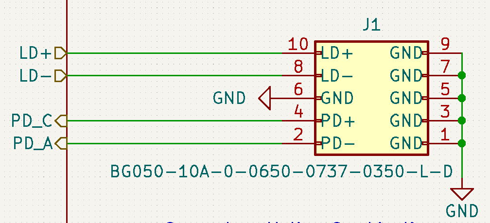
Kirdy Rev0_3:

Kirdy Adapter Type 1:
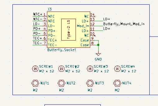
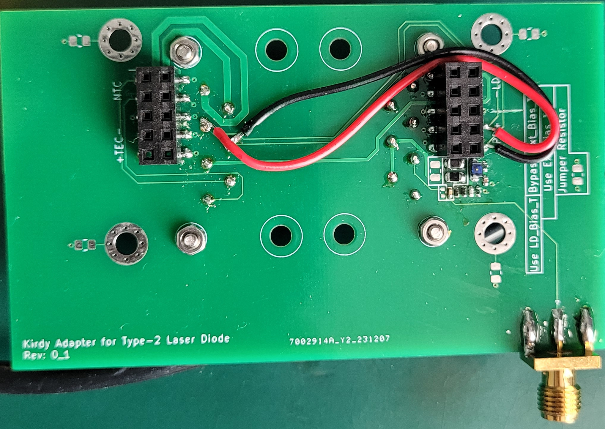
Kirdy Adapter Type 2:
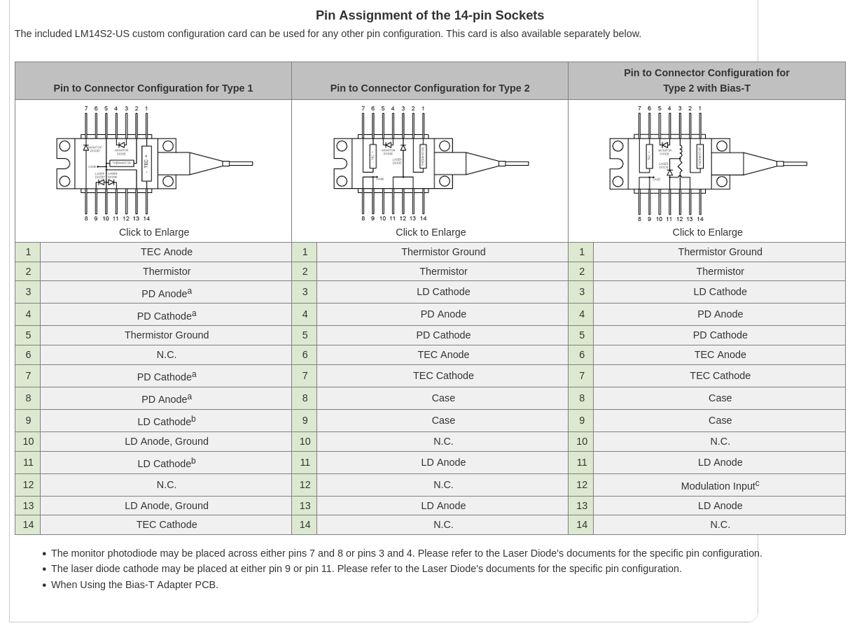
Reference Pin Connections from ThorLabs:
Hot Fix Needed:
This fix should not affect the Pd Monitor Performance on Kirdy.
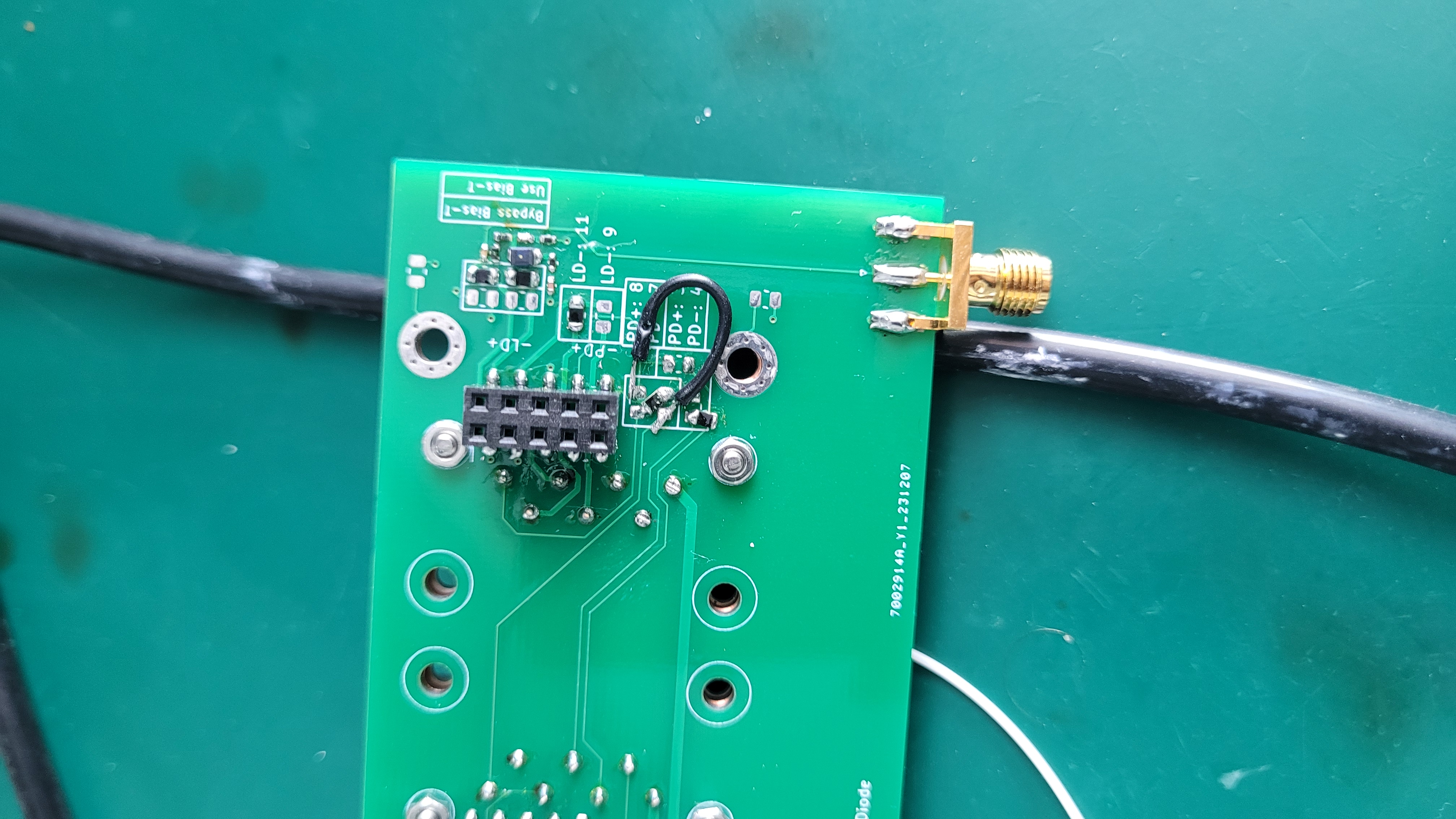
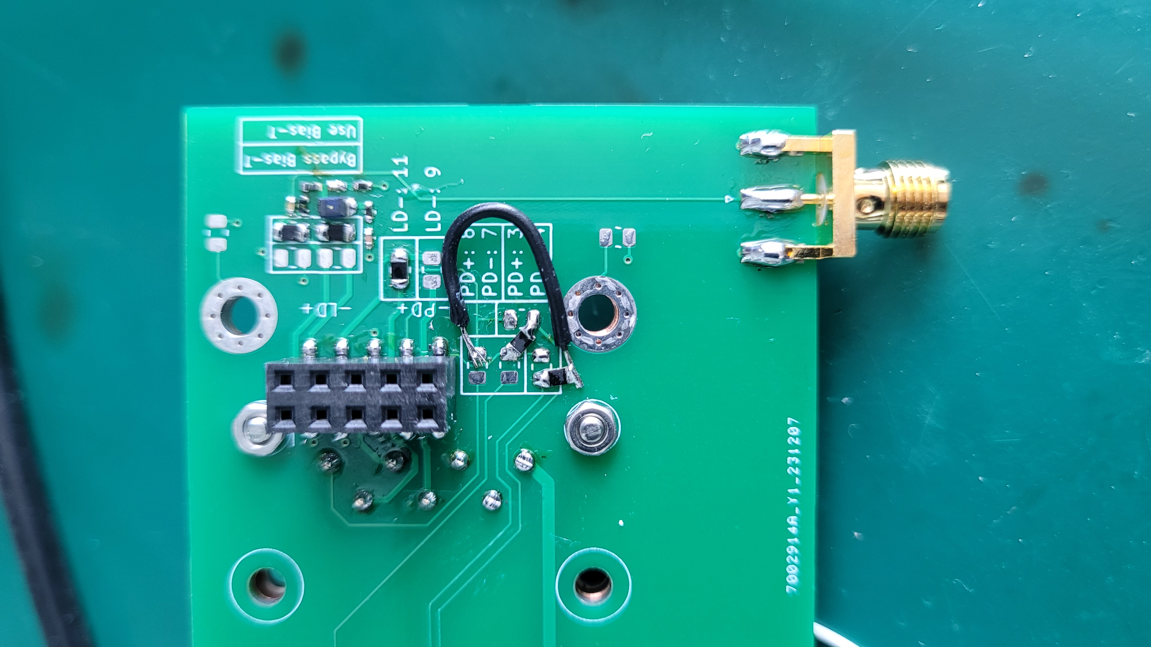
Type 1: Solder the jumper resistor and flywires in the following ways
PD Connections on Pin 7 & 8:
PD Connections on Pin 3 & 4:
Type 2: Cut copper trace of PD+, PD- and then swap the connections with flywire
Changes to be Made in Next Hw Revision:
Kirdy and Kirdy Adapter: Use PD_A and PD_K, LD_A and LD_K notations on schematics, schematics symbols and pcb silkscreen markings