1.7 KiB
1.7 KiB
Sinara 2118 BNC-TTL / 2128 SMA-TTL
JSON
{
  "type": "dio",
  "board": "DIO_BNC", // or "DIO_SMA"
  "hw_rev": "vX.Y", // optional
  "ports": [<port num>],
  "edge_counter": <bool>,
  "bank_direction_low": "input", // or "output"
  "bank_direction_high": "output" // or "input"
}
Setup
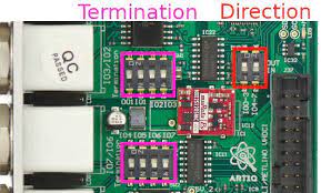
Switch the direction switches (shown on the picture below) according to customer requests. Remember, that you can only switch directions in groups of four.
Test
Output
*** Testing TTL outputs.
Outputs are tested in groups of 4. Touch each TTL connector
with the oscilloscope probe tip, and check that the number of
pulses corresponds to its number in the group.
Press ENTER when done.
Testing TTL outputs: ttl0, ttl1, ttl2, ttl3.
- Touch each TTL connector with the oscilloscope probe tip
- Adjust time- and voltage- scale and trigger threshold so that you clearly see square pulse
- Check that first TTL connector outputs 1 pulse, second - 2... fourth - 4 pulses
- Repeat 1-3 for each group of TTL connectors
Input
*** Testing TTL inputs.
TTL device to use as stimulus (default: ttl4): ttl4
Connect ttl4 to ttl0. Press ENTER when done.
...
- Mount a wire with respective connector to the chosen TTL output (any should work, choose most convenient one)
- Connect the end of the wire to the TTL input requested by the
artiq_sinara_test(you may use fast connector for SMA) - Press ENTER and check that
artiq_sinara_testprintsPASSED - Repeat 2-3 for every connector